Showing posts with label pic. Show all posts

Monday, November 12, 2012

A Silly USB Stick, It Presses 'F1'

So it happened to me. Recently I received some alert that my colocated servers were down at a local datacenter. There had been a power event where the UPS units there had failed causing a reboot of everything in this specific DC. While driving the the DC at 1am to figure out what was going on, I received alerts that some of my servers had came back up, while one had not. Upon arriving there were already a ton of people there dealing with their own equipment. Looking at my specific servers I could see there was a bad DIMM error on the front display, classically flashing orange. "All I need to do is press F1 To Continue" I thought, but unfortunately all of the crash carts were in use by other people there. Anyone who has Dell servers has seen this message during boot at some point if there has ever been any issues with their server. It is a classic error message which I wish Dell had always by default just made the server boot if possible. Because of the queue of people waiting for crash carts, I had to wait until one finally became available to press 'F1' to get my server alive. This could have easily been avoided if I had set this specific server to boot up regardless of error in the bios, but it was too late for this now.

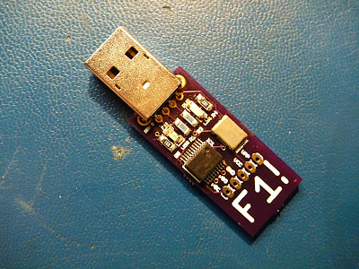
The solution? Well, make sure your servers are set to boot regardless of error in the bios. But a backup solution is my "F1 USB Stick":


What does it do? It is a UDB HID Keyboard that presses F1 repeatedly! That's all!

Simply plug it into a server and it presses F1 for you. No keyboard needed! Your server will be back up in no time.

F1!

I had fun with this one, looking at the kernel messages upon plugging in and you will see this:


usb 3-2: new full speed USB device using uhci_hcd and address 3
usb 3-2: configuration #1 chosen from 1 choice
input: Brad Boegler  Press F1! as /class/input/input3
input,hidraw0: USB HID v1.11 Keyboard [Brad Boegler  Press F1!] on usb-0000:00:1d.1-2

It is based on a Microchip PIC18F14K50 USB enabled microcontroller, a 12Mhz crystal, and the necessary passive components for operation and USB communication. I added a few LEDs in there just to be able to see what was going on. I wrote the code in Microchips C18 which utilizing Microchips USB libraries made this as simple as can be.

I will be keeping one of these in my laptop bag at all times... just in case. ;)

Thursday, February 4, 2010

Using a hard drive spindle motor for projects

I was recently staring at a pile of 15K RPM SCSI drives that had gone bad at work. I have always admired the build quality of these drives, the fact that they can spin at 15000 rpm without failure for years is amazing. I was curious if the platter spindle motors would be useful to use in any type of projects, so I tore a couple drives apart and pulled the spindle motors out of them.

These spindle motors are basically a small three phase motor. My initial assumption to drive them was that you would need to provide each phase a voltage pulse in sequence to create rotation. Looking at a drive with my scope I could see that this was definitely not the case. The waveform on each pin was extremely complex, actually so complex that all of my Agilent and Tektronix digital scopes had a hard time capturing the waveform. My best success in capturing was with my Tektronix analog scope. The waveform to one of the phases can be seen here:


This shows again how as awesome as digital scopes are, sometimes an analog scope can provide a better picture of the waveform you are trying to see. :)

To drive this motor, I wanted to see if I could get it spinning as fast as possible with the minimum amount of circuitry simply by pulsing the three phases in sequence. I chose a pic 18F4520 as the controller and was driving each phase using a TIP31C power transistor. Initially I was using a ULN2003 to drive the phases, but found the current consumption from the motor was higher than I would have liked risking damage to the ULN2003. This motor is definitely harder to drive than a typical stepper motor.


When initially starting up the motor, you need to start the pulses at a slow rate. I found that pulsing each phase at about 20Hz (1200 rpm) was slow enough to get the spindle rotating.


Once initial rotation is established you can begin decreasing the delay between pulses to increase the spindle rotation speed. Driving the motor with a square wave, I am able to reach speeds just over 100Hz (6000 rpm) before the motor begins decreasing speed.

At this point my pulses begin to overrun each other causing speed to decrease as each phase is on consecutively. Decreasing the pulse width doesn't help either as the decreased pulse width doesn't provide enough current to each winding to keep the motor running. I would like to try driving it with sine waves, or that complex waveform that the original controller generates, but 6k rpm is pretty good for the minimal circuitry required. Not bad for about an hour worth of work anyway.


I found that placing the platters back on the spindle acted as a flywheel which helped the motor maintain smoothness being driven by the pulses. To control the speed, I used an adjustable resistor to provide input into one of the adc inputs on the pic. This in turn adjusted the pulse width of the motor. Here is the code to make it spin:


#pragma config WDT = OFF

void delay1(int result1)
{
result1 = result1 / 20;
if (result1 <= 30)
{
result1 = 30;
}
Delay1KTCYx(result1);
}
void delay2(int result1)
{
result1 = result1 / 12;
Delay1KTCYx(result1);
}

void main (void)
{
int result1;
TRISB = 0x00;
while (1)
{
OpenADC( ADC_FOSC_4 & ADC_RIGHT_JUST & ADC_4_TAD, ADC_CH0 & ADC_INT_OFF, 15 );
ConvertADC();
while( BusyADC() );
result1 = ReadADC();
CloseADC();


PORTB = 0b00000001;
delay1(result1); //big
PORTB = 0b00000000;
delay2(result1); //short
PORTB = 0b00000010;
delay1(result1); //big
PORTB = 0b00000000;
delay2(result1); //short
PORTB = 0b00000100;
delay1(result1); //big
PORTB = 0b00000000;
delay2(result1); //short
}
}


Next I plan creating a simulated sine wave with the pic to try to obtain higher speeds and smoothness replicating what the hard drive controller circuity does. I would like to look into the pulses generate by the actual hard drive controller as well to get a better understanding of how it can reach speeds of 15000 rpm.

Saturday, August 8, 2009

One sweet ADC, National Semiconductor ADC08100

I spent this weekend playing with a few analog to digital convertors I have been meaning to try out, one of which is the National Semiconductor ADC08100. The ADC08100 is an 8 bit 100Msps ADC with very low power operation. To test it out I have it clocked from a PIC18F4520 running at 40Mhz and has the output being displayed on a pair of HP hexadecimal displays. Input is coming from a small Murata pot whose voltage can be adjusted over the set range of 0V to +3V.


I plan on using these ADCs for everything from video capture in basic machine vision systems to any type of ADC that needs high speed accurate conversion that can offload the ADC operation from the microcontroller itself.

Thursday, July 2, 2009

TCM8230MD Camera Images Within Reach

Last night I was able issue a start command over I2c to the TCM8230MD camera module to have it start sending images. I'm now receiving valid YUV 422 data off of the 8 bit bus along with the necessary clock and sync pulses.


This camera is definitely not the easiest thing to work with. The datasheet is not as clear I would have liked and the timings necessary for the startup sequence took a little bit longer to figure out than I had expected.


The next step will be to be to send the camera a few more control codes to lower the frame rate and resolution to get the data rate to a more manageable level for the pic. I'm hoping to capture and display my first usable image over the weekend.

Sunday, May 31, 2009

Automatic plant watering system, Part II

Last summers automatic plant watering system worked well, but it never ended up leaving the breadboard. So as I already have my pepper plants planted for this year, I wanted to get a more permanent system up and working. I took the design from last year and built it on a Rabbit Flex dev board I have had laying around since I had used the rc3400 I built last years on for a separate project. One of the nice parts of this board is that it has on-board Ethernet which I plan to take advantage of.

This version will have a web based interface to allow me to control the watering times remotely. Along with the rain detector that was built last year, it will also have temperature and humidity sensors that will allow me to adjust watering accordingly based on current conditions. Ideally it will also be able to show how much water I am using per day once I calculate the flow rate of my system.

Design:


The basic system is operational right now along with the external sensors, the web interface is the last step of the project, along with a case to mount the project in.

Monday, November 17, 2008

New PIC Programmer

My new Microchip PIC programmer arrived today. I have been meaning to get a USB powered version for awhile now since my new bench machine only has two serial ports... causing the rs-232 real estate to be rather limited. (plus I can't use my ISA serial cards in machines now that the ISA bus is pretty much obsolete ). Instead of going the expensive option, I went the cheap Chinese option and ordered a PICkit2 compatible programmer off of eBay. It took about two weeks to arrive directly from Honk Kong, but it's here and it works.

Of course after opening the package I noticed that it was missing the ZIF sockets. :(


Looking back at the auction I see that this was stated in the description in a non-descriptive Chinese kind of way. Luckily the sockets are cheap and I ordered them from a reputable supplier today.

This will allow me to start using the surplus of samples I have been ordering for free and let me explore the PIC world a little more. I have been spending a lot of time in the AVR ATmega world for the past month or so (most ATmega's don't require a programmer) so it will be cool to compare and contrast the two micro families.