Showing posts with label project. Show all posts

Friday, May 8, 2015

Large Display for GPS Disciplined Time Server


Since building my own GPS disciplined local time server I have wanted a large display of some sort to display my super accurate clock. The primary purpose of doing this was really just because it would be rally really cool looking. I also have a personal issue with any clock that does not set itself from the WWVB or support NTP, in 2015 we shouldn't have to manually set clocks anymore. A secondary use for doing this would be for ham radio purposes. A nice large clock that is always accurate so I can easily and quickly log contacts in UTC would be very useful. Ultimately I ended up with a very nice solution and here is the result:

ESE ES-166 timecode display used for GPS clock

Searching for someone who makes such a clock was frustrating. It seems either you can have a large format clock for cheap that does not support NTP, or you can have one that does support NTP but costs hundreds of dollars. Designing and building my own was the next option that I had considered for awhile. A simple PIC based device that drives some large 7 segment led displays would be trivial to build, but I couldn't get into the project. It just didn't excite me, It's one of those things that would be so simple and mundane that I just couldn't drive myself to do it. It would be like a software engineer being assigned the task of writing a word processor. It's already been done so many times and is such an unfulfilling project you can just never get excited about it.

So on to Plan C. Let's see what's already available and either modify or make it work for my intended use. Basically I would be looking for a large LED, backlit LCD, or big VFD display of some sort that would be able to easily display time. Input can be via various means, ethernet or serial would be first choices, some other parallel type interfaces would be not ideal although I could still make it work if needed. Luckily having some experience is professional video editing when I was in college, I looked towards something I felt might me the perfect solution: Timecode displays.

Upon scrounging around I found a perfect device on eBay, an ESE-166 remote timecode display. These can be found for less than $50 at times are are beautiful pieces of gear. It is a big 2U rack mount enclosure with a nice large format LED display on the front panel. This display is designed for displaying accurate time code for video editing systems. The particular display I purchased had hour, minute, and second digits which would be perfect. Many time code displays also include a 4th digit section for frames which this one did not as I did not need it for my purpose. The inputs on these devices are typically a single 75ohm timecode serial input for SMPTE timecode. I was fine with this as designing some hardware to convert an rs232 serial stream to SMPTE timecode actually sounded pretty fun, but I ended up not needing to. This specific display also included an rs232 serial input that supports a few ASCII time formats. This would be a perfect solution, just have a script that takes my local time directly off of the time server itself and dump it out the serial port to this display. There would be some very minimal latency with this obviously, but regardless this solution would be perfect! The ASCII format I chose to use is as follows:

Format #0: (CR)(LF)I(^)(^)DDD(^)HH:MM:SS(^)DTZ=XX(CR)(LF)

As for getting the time data into the ESE, it has two runtime options set by some dip switches inside. The first is a free running clock that when the serial port receives a time string, it updates the internal clock to the time received. The second option does not free run, you simply continuously provide the time signals to update at the interval you specify. In this option, you would need to provide the time signal at least once a second to keep the display real time. For now, I went with the first option. I have the ESE free running with a cron dumping data from my NTP server sending an rs232 time string via cron every five minutes. The noticeable time drift of this clock over a five minute period is not noticeable at all and this solution keeps the clock up to date on five minute intervals without having to constantly send it serial data.

For those that are curious what is inside the ESE ES-166, it is pretty basic:


There is a whole lot of room in that chassis with not very much there. Just a mains transformer and simple analog rectified power supply with a handful of logic to decode the SMPTE / serial port data and drive the display. I'm planning on moving my Trimble GPS receiver inside of this case as there would be plenty of room for it. This would consolidate some of the hardware laying in the back of my server rack.

Additionally the manual for the ES-166 includes a schematic which is also nice to see. There was one part of the design that I really loved, the rs232 to TTL translation:


There is no serial driver there, MAX232 or equivalent. Just a simple level converter based on a 2n2222 with a diode and resistor. I love it! You see MAX232s in everything these days when they are often just not needed for serial RX conversion.

Further plans include racking this unit in my server rack and possibly getting a second unit so I can display both local time and UTC.

Friday, December 5, 2014

Stratum 1 Time Server Based on a Trimble Placer GPS 450 with PPS Output

Setting up GPS disciplined stratum-1 timeservers are not a new or technically difficult task, plenty of articles are already available including some excellent ones from David Taylor's satsignal.eu site. The basic idea behind using a GPS device as a stratum-0 reference is the ability to have a very low latency and low jitter accurate local time source. The only complicated part is finding or modifying a GPS receiver that can provide a precise 1 pulse per second source.

This post is going to focus on a simple, inexpensive, and somewhat elegant solution based on a Trimble Placer 450 GPS receiver. The Trimble 450 is by no means a modern device. It was originally produced in the 1990s and used within vehicles for fleet management purposes. It is large compared to modern units and is also only an 8 channel receiver that uses only satellites in the US GPS satellite constellation. The reasons why I really like the Trimble 450 are that is is very rugged and well designed (as it was to be used in the field). It can also run off of a wide voltage supply range and it is easily modified for a true precise 1 pulse per second (PPS) output which is the key part to having an accurate stratum-1 time server.


Trimble Placer GPS 450s are plentiful (there are available on eBay all the time for less than $15 including shipping). I had a unit myself sitting in a parts box for maybe 10 years that I picked up somewhere for free, this is why I went with this unit to begin with as my time source. I also love re-purposing old and somewhat obsolete inexpensive hardware. You will need an external active GPS antenna to use with it, any cheap ones from China will work, the one I purchased was $6. Note you will need an antenna with an MCX connector (or adapter) to interface to it. One additional nice thing about the 450 is you can easily replace the on-board MCX connector with an SMA, BNC, etc if you wish.

By default the Placer 450 outputs a Trimble ASCII Interface Protocol (TAIP) serial datastream, but this is easily changeable to NMEA-0183 strings. Going through the docs I believe gpsd is capable of decoding TAIP messages, but I didn't spend the time to try. TAIP is a binary format and while it is a brief and compact data format, I like the human readable NMEA output strings as they can provide visual output of  your GPS devices status. The Placer 450 can be switched to NMEA with the following commands:

       
>SPR:NMEA=TT<
>SRTSAVE<


Once switched to NMEA, it will provide the following standard strings: GPZDA, GPGGA, GPGLL, GPGSA, GPVTG, and GPRMC. I recommend reading the Trimble Placer 450 manual as it does have good information if you are unable to successfully communicate to the device via RS-232. There is also an old dos based configuration utility available that you can use to program it and switch its output to NMEA format. You will need a machine running win98 or older to run it though. I keep an ancient Pentium 133 machine around for programming old Motorola radios and I had no issues using it for programming the 450.

If your Placer 450 has been sitting around for years without being used, its internal GPS almanac is going to be extremely outdated. This resulted in a cold start of mine taking about an hour to finally acquire four satellites for 3D navigation and update its GPS almanac. Any subsequent warm starts after this will lock on within about 60 seconds. This would also be a good time to check the internal lithium battery. The memory in the Placer 450 is volatile and if the battery is bad every power on will result in a cold start. Checking on my receiver, the battery was fine.

PPS Output

Utilizing the PPS output of a GPS receiver is really the most important part of having a truly disciplined stratum-1 time server. Not all GPS receivers offer a true 1-PPS reference, fortunately the Placer 450 does, it just isn't where it needs to be. While the NMEA strings that come off of the GPS receiver contain accurate time data, various delays through the serial communication result in a time reference that has significant latency and jitter. This usually ends up being no better time keeping than just pointing your time server to another stratum-1 server. That said, the GPS time is still useful for events where internet connectivity is lost or unreliable.

The PPS output provides an extremely accurate time pulse that occurs once per second. Ntpd ( or your time server software of choice) can use this pulse to keep extremely accurate time. I will only be discussing the integration of ntpd in this post. The Placer 450 does indeed have a PPS output, unfortunately this output is on a separate DB-9 data connector. Probing its output on a scope, this pulse is clearly visible and has a very fast falling edge when it occurs (1.1 microseconds on average).


Now that we know we have an accurate PPS pulse, we need to get it into the computer running ntpd as quickly and with as little latency as we can afford. The solution to this is to send the pulse across the serial port on an unused pin (data carrier detect is standard to use in this case) which will drive an interrupt on the ntpd machine. In regards to the Placer 450, I decided to take this negative edge pulse, feed it into a max232 serial driver and send it down the unused DCD pin on the serial port. This worked perfect as the max232 inverts the data and results with a positive ~+15V RS-232 compliant pulse. The final setup of this is shown here:


The small blue board I added contains the max3232c serial driver and necessary charge pump capacitors. I pulled +5 volts off of a positive rail on the Placer 450 along with ground. Since the DCD pin on the RS-232 connector was unused, this modification was very simple. I also removed the original 3 pin power connector and hardwired it to +12v as there is no reason to worry about sourcing an original power cable. Since these devices are usually pulled from service, the original wiring harnesses usually never stay with the unit. Here is the resulting outgoing pulse through the max3232c:


Now that we have the pulse going to the NTP server via the DCD pin over RS-232, we need to verify its operation. Any modern Linux distribution will have PPS support built into the kernel, the serial module for PPS will just have to be loaded. To verify the arriving pulses, you can use pps-tools which is available for most distributions. The following output from ppstest shows my arriving 1 PPS pulse indicating my hardware modification is working.

       
[root@time01 ~]# ppstest /dev/pps0
trying PPS source "/dev/pps0"
found PPS source "/dev/pps0"
ok, found 1 source(s), now start fetching data...
source 0 - assert 1417642033.999999820, sequence: 226503 - clear  1417642033.000028598, sequence: 173333
source 0 - assert 1417642035.000000722, sequence: 226504 - clear  1417642034.000021949, sequence: 173334
source 0 - assert 1417642035.999999642, sequence: 226505 - clear  1417642035.000022821, sequence: 173335
source 0 - assert 1417642036.999999339, sequence: 226506 - clear  1417642036.000023328, sequence: 173336


One note regarding serial to USB adapters. I was using one initially and was not seeing the pulse arriving on my machine. Once I switched to the onboard serial port (/dev/ttyS0) my pulses were immediately visible. If you are going to use a USB adapter, make sure that it supports the DCD pin as mine did not.

A few more prerequisites are needed including having gpsd installed along with ntp. The ntpd configuration is really the last critical step, in the case of my Placer 450, the following configuration is used:

       
# GPS reference
server 127.127.28.0 prefer
fudge 127.127.28.0 refid GPS

# PPS reference
server 127.127.22.0 minpoll 4 maxpoll 4
fudge 127.127.22.0  flag3 1  refid PPS


How this configuration works and what it should be set to could be an entire separate discussion, luckily it is documented very well. Basically the ip addresses shown above are driver interfaces to the gps NMEA serial interface and the kernel PPS. Once ntpd is restarted, checking ntp's status you will see the following:

       
[root@time01 ~]# ntpq -p

     remote           refid      st t when poll reach   delay   offset  jitter
==============================================================================
-time3.chpc.utah 198.60.22.240    2 u    2   64  377   71.766   14.708   0.200
-time.tritn.com  66.220.9.122     2 u   39   64  377   71.081    2.188   3.051
+segfault.boom.n 216.218.254.202  2 u   25   64  377   45.549   -4.891   0.548
+50.7.72.4       128.138.141.172  2 u   31   64  377   58.978   -4.452   0.654
*SHM(0)          .GPS.            0 l    8   64  377    0.000  -71.444   4.780
oPPS(0)          .PPS.            0 l   12   16  377    0.000   -0.001   0.001


A few things to note in the above output:

1. Both the GPS and PPS sources now show up in the ntp output.
2. The tally flag for the GPS source is '*' indicating it is a system peer.
3. The tally flag for the PPS source is 'o' indicating the system sync is derived from a PPS signal.
4. Jitter on the PPS source is significantly lower than the other network based sources.
5. The jitter and offset for the GPS source are higher than other sources, this is expected as the serial communication latency between the Placer 450s NMEA strings and server is not guaranteed.

The next steps are to monitor and log the time servers accuracy and precision over time to see how much drift there is with the GPS source and without. After some basic testing it seems to be much improved but only time will tell.

Tuesday, May 21, 2013

Experiencing the Dayton Hamvention 2013

The Dayton Hamvention was this past weekend (May 17th - 19th) and after many years of wanting to go and not going for various reasons, I finally planned a day to spend there. This was also the first one since I received my ham radio license last year which gave me another excuse to go.

The Hamvention is an enormous ham radio swap meet that has been going on since the 1950s. While ham radio is a huge part of it, general electronic components are everywhere, so it is suitable for anyone who loves electronics. While I would have loved to get there on Friday morning to be one of the first ones looking for deals, prior work commitments forced my visit to occur on Saturday. The day started by leaving my house at roughly 6:00 am from Michigan to drive about 220 miles down to Dayton Ohio. The weather forecast for the day was sketchy at best with a 50% chance of rain all day, I decided to get there as early as possible to hopefully beat any rain. The location was easy to find, just a few miles off of I-75 and the towering antennas made it easy to spot. Upon arriving around 9:30 am, there was no rain and still plenty of parking in the field across from the venue, Hara arena.


After my initial ticket purchase at the front doors, I headed straight for the outside market area as there was no rain at this point and I wanted to start hunting for anything good before all the great items were picked over. Upon walking outside into the huge outdoor swap meet, the initial experience was overwhelming! The size of the outdoor swap meet was just enormous.


I started at the front and started hitting every row of booths on the east lot, followed later by the west lot. There was just so much good stuff! There was a lot of junk there too. Things like late 1990s computer hardware, old giant two-way radios, and random assorted telco hardware from the 1980s. I would say about 75% of the booths (a booth could be just the bed of someones truck piled full of electronics) contained interesting stuff. You would find people with just boxes and boxes of the strangest things. About an hour into the day the rain did start falling, so I browsed into one of the larger tents for a bit.

Meters!
Once the rain subsided, I began more browsing. The selection of hardware and components was terrific. Looking for RF components was not an issue, the stuff was everywhere so I was extremely happy. Everything from new MMICs and cables / connectors to older used random brick oscillators and waveguides.


Later that morning I spent some time browsing the inside exhibits, all the big radio brands were there (Icom, Yaesu, Kenwood, Alinco, etc). The DZKit guys were there too with their Sienna HF Receiver/Transceiver kit which was really impressive. It's a very high-end HF transceiver that you assemble. Most of the smd work comes completed on the boards, another 40 or so hours of assembly is required to complete including stage by state testing.

Mini-circuits had a booth there, being one of my favorite RF component suppliers I had stopped by to talk to them for a bit. I also talked with the Society of Amateur radio Astronomers along with the AMSAT people. I was happy to learn that their upcoming Fox-1 Satellite has an actual launch date scheduled in 2014. This satellite will carry a handful of experiment payloads along with the best part, an FM repeater. It will be nice to have a second working FM sat available besides SO-50.


A little after noon I met up with Chris Gammell of The Amp Hour podcast, it was the first time meeting him which was awesome after listening to the show for almost two years. We browsed around the booths for the rest of the day talking about everything electronic and looking for bargains. A little bit later that day we also met up with Dr. Gregory L. Charvat who was a guest on The Amp Hour which was equally as awesome. I had a bunch of questions for him regarding my radio telescope project, he was really informative and a great person to talk about RF to while browsing random electronic bits.

Towards the end of the show at 5:00 we started looking for any last deals before people started packing up their gear. While I didn't find anything, Chris came across an old HP frequency generator in perfect condition for $10. A lot of exhibitors who were not sticking around for Sunday starting just dumping stuff they didn't want in the trash. Some of it was scavenged by people, but most of it wasn't worth carrying back to the car even for being free.

As for my own purchases, I only ended up buying a few things: some SMA hardlines and cables, a nice brass WR-90 waveguide about 16" long (perfect for a 10Ghz slot antenna), a few mini-circuits attenuators, and a large lot of aluminum hardware (hexagonal standoffs and such). Looking back, I keep thinking about things I should have bought, but did not. I definitely needed more than a single day for this!

After 5:00 when the show was over for the day, a bunch of us headed over to a local bar which Chris had previously planned. There were about 20 people that had showed up total, most are other fellow Amp Hour listeners which was very cool. Shortly after 6:00 I decided to start heading home as I was completely exhausted, but not before Chris tore into his frequency generator to take a look inside.


Lessons learned:

Next year, arrive on Friday morning. I felt like a lot of booths tables had a lot of empty spots where gear had been sold. It seemed like everything good (test equipment and radios) was already gone by Saturday morning.

Bring a rolling luggage cart. I had one but forgot to throw it in my trunk. If you purchase anything heavy, it's a long walk back to the car.

And definitely spend more than one day there. A single day is not enough time to see everything. I probably only saw a quarter of the inside booths and still missed a bunch of stuff outside as well.


Monday, November 12, 2012

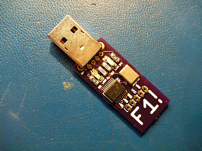
A Silly USB Stick, It Presses 'F1'

So it happened to me. Recently I received some alert that my colocated servers were down at a local datacenter. There had been a power event where the UPS units there had failed causing a reboot of everything in this specific DC. While driving the the DC at 1am to figure out what was going on, I received alerts that some of my servers had came back up, while one had not. Upon arriving there were already a ton of people there dealing with their own equipment. Looking at my specific servers I could see there was a bad DIMM error on the front display, classically flashing orange. "All I need to do is press F1 To Continue" I thought, but unfortunately all of the crash carts were in use by other people there. Anyone who has Dell servers has seen this message during boot at some point if there has ever been any issues with their server. It is a classic error message which I wish Dell had always by default just made the server boot if possible. Because of the queue of people waiting for crash carts, I had to wait until one finally became available to press 'F1' to get my server alive. This could have easily been avoided if I had set this specific server to boot up regardless of error in the bios, but it was too late for this now.

The solution? Well, make sure your servers are set to boot regardless of error in the bios. But a backup solution is my "F1 USB Stick":


What does it do? It is a UDB HID Keyboard that presses F1 repeatedly! That's all!

Simply plug it into a server and it presses F1 for you. No keyboard needed! Your server will be back up in no time.

F1!

I had fun with this one, looking at the kernel messages upon plugging in and you will see this:


usb 3-2: new full speed USB device using uhci_hcd and address 3
usb 3-2: configuration #1 chosen from 1 choice
input: Brad Boegler  Press F1! as /class/input/input3
input,hidraw0: USB HID v1.11 Keyboard [Brad Boegler  Press F1!] on usb-0000:00:1d.1-2

It is based on a Microchip PIC18F14K50 USB enabled microcontroller, a 12Mhz crystal, and the necessary passive components for operation and USB communication. I added a few LEDs in there just to be able to see what was going on. I wrote the code in Microchips C18 which utilizing Microchips USB libraries made this as simple as can be.

I will be keeping one of these in my laptop bag at all times... just in case. ;)


Monday, October 8, 2012

Hydrogen Line 1.42Ghz RF Front End - Radio Astronomy

After finally completing the power supply for my RF front end last week, I spent some time tonight assembling the power supply onto the back of the feedhorn assembly and wiring all of the amplifiers and downconverter to the necessary voltage supplies. Here is a look of what it currently looks like:


From the front, you have the feedhorn, LNA, 1420Mhz cavity filter, downconverter, low pass filter, second LNA, then the power supply on the very back. Now that it is completed, I performed some testing tonight to check operation, sensitivity, and power supply stability. So far everything is looking good, the video below shows its operation on my bench for testing purposes:


Saturday, September 29, 2012

Radio Telescope Power Supply - Progress

Today I received my power supply boards for the RF frond end of my radio telescope. Due to the number of amplifiers and the voltage requirements of my downconverter, I needed a supply that provided a stable and clean +5V, +10V, +12V, +15V, and adjustable 8V to 15V output.


Current requirements on all outputs is very small (less then 20mA at each respected output) with exception of the 12V supply which powers the mini-circuits ZRL-2400LN low noise amplifier. It has a 350mA @ 12V requirement so I have utilized the aluminum enclosure to sink some heat off of the 12V regulator. I slightly miscalculated the boards size for the aluminum enclosure I had chosen to use for it. Due to the mounting standoffs inside the case, I was not able to mount the board flush against the side of the enclosure... although it was nothing a band saw couldn't fix. All voltage outputs are passed through the enclosure using feed through capacitors.

There is nothing really exciting about this supply other than the fact that it is now completed. Power supplies are probably the least exciting components of any project to build, even though their importance and stability are critical. Now that it is completed I can install it on the back of my RF frontend and start prepping the actual mount for the dish.

Here is the final assembled board mounted in its shielded enclosure:


Saturday, August 11, 2012

New 10Ghz Oscillator

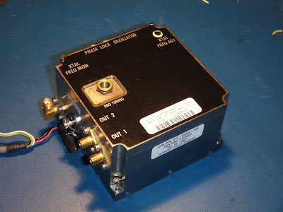
I have been needing a stable 10Ghz oscillator for a few projects I have been working on and was able to pick this brick up for pretty cheap. This is a Digital Microwave Corp 10.210763 GHz phase locked oscillator. This unit consists of a dielectric resonator oscillator that is phase locked to the x100 harmonic of a 102.10763 MHz crystal.
 

10Ghz PLL oscillator

While not a YIG, it should be more than stable enough for my needs now (I hope). The new 10Ghz project will be coming after I finish up my 1420Mhz front end for the radio telescope which is nearing completion :)


Friday, July 6, 2012

Radio Astronomy Hydrogen Line 1420Mhz RF Front End Testing

I have been building the RF front end for my radio telescope for a few weeks now and am finally at a point where I can sit down and test it. Right now I have the feedhorn assembly completed and the necessary front end electronics mounted to the back of it.

The feedhorn feeds directly into a mini-circuits ZRL-2400LN low noise amplifier. The output of this then feeds into a cavity filter with a center frequency of 1420Mhz. This was a rare but exciting eBay find hat I came across a few years ago, it actually had come off of the VLA in New Mexico. It had been originally tuned to 1430Mhz but with the assistance of a VNA I was able to tune it down to 1420Mhz. This then outputs to my own custom built downconverter which I have mounted in a custom copper enclosure. I will eventually mill a aluminum enclosure for it but this will suffice for now. Finally after the amplified output stage on my downconverter, I pass the IF through a mini-circuits SLP-450 low-pass filter to remove the original source frequencies, LO, and image frequencies. For testing I have my LO set to 1200Mhz which will result in a 220Mhz IF based on the 1420Mhz source. Ideally I will probably downconvert to 70Mhz as there is plenty of 70Mhz detection gear available on the surplus market. I'm still most likely going to build my own I/Q demodulator for the detection side.

Here is a quick video demonstrating the testing setup:


Thursday, January 19, 2012

21cm Line Downconverter Testing

This project is the heterodyning downconverter I have designed and assembled for radio astronomy purposes. It will be used to convert 1420Mhz Hydrogen Line reception from my 10' dish and feedhorn / LNA assembly down to a more manageable frequency of 100Mhz or so. It consists of a mini-circuits mixer along with a Z-Comm VCO for the LO. This particular VCO has a frequency range of 850Mhz to 1600Mhz, ideally covering the 1420Mhz band. A few mini-circuits low noise mmics are used for amplification along with a mini-circuits low pass filter to filter out the original LO and source frequencies.

Last week after returning from vacation I received my downconverter boards and started assembly. Here is the final assembled downconverter ready for testing:


This downconverter as I began testing has excellent performance. I need to do some further testing and measuring to calculate its noise and gain, but I have been very pleased so far. Because of the flexibility of the VCO, I have had some fun during testing downconverting and also upconverting various frequencies around, the following video show upconversion of FM bands to 900Mhz:

Friday, November 18, 2011

ALTERA EPM3032A CPLD Breakout Board

Recently I came across a large quantity of NetApp DS14 Filers that were being disposed of which are basically Fiber Channel shelves full of FC drives. While a few of these ended up in my basement 48U rack for FC attached storage, the rest I scavenged as many parts from as possible. These shelves have removable modules depending on the interfaces required. On these modules two parts caught my eye:


Two ALTERA CPLDs from the Max 3000 family. An EPM3256A and an EPM3032A. While I was excited about both devices, the EPM3032A I was initially more excited for as it is a more manageable package size.

After removing about 10 or so of these CPLDs from the boards I went ahead and designed a simple breakout board in Eagle. All 44 pins are broken out and I included an onboard 3.3V regulator along with a JTAG connector. Upon receiving the boards I threw one together, wrote a simple 4 bit counter in VHDL in Quartus II and downloaded to the CPLD via JTAG to see it worked perfectly.


The EPM3032A is not a large CPLD, with only 32 macrocells it's by no means a device for large scale logic implementations. The 4 bit counter ended up using 4 macrocells or 13% of the usable space in the CPLD, but it is perfect when you need a small custom logic device where many individual chips would be required. I'll be working on a breakout for the more powerful EPM3256A soon.

Tuesday, March 23, 2010

Maxim MAX7456 On Screen Display

While looking for a solution to display characters over video for an on screen display I came across the Maxim MAX7456. This is one easy to use chip for exactly this purpose. Using a SPI bus it is easily interfaced with a PIC microcontroller (I'm using a PIC18F2520 for testing).

I have just started playing with this chip and have discovered how easy and powerful it is to use. I have one project in mind for it that I am starting on now and will post again once it is further developed.

Thursday, February 11, 2010

Serial VFD character displays are awesome

I finally spent a few minutes powering up the serial VFDs I bought a month or so ago, they are all working. :)


And it's bright! :D Placing a filter over the front will increase contrast and make it much easier to read in bright conditions.

I will say that these are by far the easiest displays I have ever worked with. Powered it up with 5V, wired it through a max232 to my machine, 19200, 8,1,1 was its default serial config and it was running. Any text to the terminal showed up on the display. Special codes can place cursor and clear the display. With a little extra work you can write custom characters to the displays memory. Interfacing these with any microcontroller will be so easy and will save a bunch of io pins and code space not having to interface HD44780 compatible displays via a parallel interface.

Thursday, February 4, 2010

Using a hard drive spindle motor for projects

I was recently staring at a pile of 15K RPM SCSI drives that had gone bad at work. I have always admired the build quality of these drives, the fact that they can spin at 15000 rpm without failure for years is amazing. I was curious if the platter spindle motors would be useful to use in any type of projects, so I tore a couple drives apart and pulled the spindle motors out of them.

These spindle motors are basically a small three phase motor. My initial assumption to drive them was that you would need to provide each phase a voltage pulse in sequence to create rotation. Looking at a drive with my scope I could see that this was definitely not the case. The waveform on each pin was extremely complex, actually so complex that all of my Agilent and Tektronix digital scopes had a hard time capturing the waveform. My best success in capturing was with my Tektronix analog scope. The waveform to one of the phases can be seen here:


This shows again how as awesome as digital scopes are, sometimes an analog scope can provide a better picture of the waveform you are trying to see. :)

To drive this motor, I wanted to see if I could get it spinning as fast as possible with the minimum amount of circuitry simply by pulsing the three phases in sequence. I chose a pic 18F4520 as the controller and was driving each phase using a TIP31C power transistor. Initially I was using a ULN2003 to drive the phases, but found the current consumption from the motor was higher than I would have liked risking damage to the ULN2003. This motor is definitely harder to drive than a typical stepper motor.


When initially starting up the motor, you need to start the pulses at a slow rate. I found that pulsing each phase at about 20Hz (1200 rpm) was slow enough to get the spindle rotating.


Once initial rotation is established you can begin decreasing the delay between pulses to increase the spindle rotation speed. Driving the motor with a square wave, I am able to reach speeds just over 100Hz (6000 rpm) before the motor begins decreasing speed.

At this point my pulses begin to overrun each other causing speed to decrease as each phase is on consecutively. Decreasing the pulse width doesn't help either as the decreased pulse width doesn't provide enough current to each winding to keep the motor running. I would like to try driving it with sine waves, or that complex waveform that the original controller generates, but 6k rpm is pretty good for the minimal circuitry required. Not bad for about an hour worth of work anyway.


I found that placing the platters back on the spindle acted as a flywheel which helped the motor maintain smoothness being driven by the pulses. To control the speed, I used an adjustable resistor to provide input into one of the adc inputs on the pic. This in turn adjusted the pulse width of the motor. Here is the code to make it spin:


#pragma config WDT = OFF

void delay1(int result1)
{
result1 = result1 / 20;
if (result1 <= 30)
{
result1 = 30;
}
Delay1KTCYx(result1);
}
void delay2(int result1)
{
result1 = result1 / 12;
Delay1KTCYx(result1);
}

void main (void)
{
int result1;
TRISB = 0x00;
while (1)
{
OpenADC( ADC_FOSC_4 & ADC_RIGHT_JUST & ADC_4_TAD, ADC_CH0 & ADC_INT_OFF, 15 );
ConvertADC();
while( BusyADC() );
result1 = ReadADC();
CloseADC();


PORTB = 0b00000001;
delay1(result1); //big
PORTB = 0b00000000;
delay2(result1); //short
PORTB = 0b00000010;
delay1(result1); //big
PORTB = 0b00000000;
delay2(result1); //short
PORTB = 0b00000100;
delay1(result1); //big
PORTB = 0b00000000;
delay2(result1); //short
}
}


Next I plan creating a simulated sine wave with the pic to try to obtain higher speeds and smoothness replicating what the hard drive controller circuity does. I would like to look into the pulses generate by the actual hard drive controller as well to get a better understanding of how it can reach speeds of 15000 rpm.

Thursday, January 7, 2010

Updates and new serial VFD modules

I'm finally moved in the new place, unfortunately there has been a lot of 'home things' that needed attention that have pushed back my electronic and software projects. I have been setting up my benches and unpacking my equipment this week in the new basement work area which I am very excited about. I should actually be able to start getting back into things this coming week.

Today my new serial VFDs showed up which has me pretty excited:


They are two line by 20 character display with both an 8 bit 5v parallel and up to 19200bps serial interface. Vacuum fluorescent displays just have a nice glow to them that contrasts the typical look of an LCD display you see today. I plan on using one as a primary display interface for my CPU project among other things.

Thursday, October 1, 2009

CPU From Scratch

I haven't been posting too much lately, mostly because I have taken on a very ambitious project. I have decided to create an entire CPU from scratch using only TTL based logic. This project has been in the works for about two months now and I finally have something to show for it. Because this project is going to be more in-depth than most I have dedicated an entire wiki to it which can be located at bradthx.net.


As it stands now I have an 8-bit CPU that is able to load and store instructions into address and instruction registers from memory. This proves (along with a lot of additional debugging) that my design seems solid and I can begin designing my opcode and burning it to eproms. I will update this blog when I make major milestones, but all the technical data will be located at bradthx.net.


Sunday, September 20, 2009

Power Supply Reverse Engineering

I recently came across a crazy good deal on eBay, a Scientech SP1000 precision balance / scale. For $15 I couldn't refuse the purchase of a retail $2000 precision scale even though I knew the power supply was not included with the unit. I figured I could just reverse engineer the circuitry to create my own external power supply ( $100 retail value for the power supply from Scientech) to be able to use the scale, and after an hour on my bench my assumptions were correct.

I have wanted a simple scale for awhile now to measure the weight of rocket components to be better able to predict it's performance with my addition of GPS / accelerometer payloads. There are a ton of cheap scales on eBay (mostly from Chinese suppliers) but I knew I wanted something better and more precise than the average drug dealer who purchases these cheap items. After some research I discovered Scientech was one of the leaders in precision balances and began to search for them. I was very happy to find one for very cheap with the absense of a power supply. This is where my reverse engineering began. The scale had a 5-pin din connector for power. Knowing that this was not going to be completely simple, I tore the unit apart.

To reverse engineer it's power input, I first located it's ground pins. I did this by locating known ic's and metering their ground pins to a pin on the power connector. Also noticing large ground planes on the board helped as well. There ended up being two grounds pins on this board. Two pins down, three to go. Once the two ground pins were identified, I went for non-ground voltages. The first I discovered was a +5v line. I traced the pins back through taces from some known 7400 TTL logic ic's and was able to identify a +5v input. So one pin from the power supply provided +5v.


Moving forward I was lucky to find a label on the board indicating -12V. I followed this trace back to the power connector and identified one pin as being definitely -12V. Another pin from strictly an assumption would be +12V. I followed the traces from this last pin around and discovered they followed the -12V traces to a regulator, indicating that my assumption was probably correct. Time to power up.


After making all connections to my power supply, i powered up the +5V line first. Pressing the power button resulted in the display turning on with '-----'. A good start. I set my +12V and -12V supplies to current limit at .1A as to not burn it out if I was wrong, and slowly raised the voltage on each. Once about 10V on each was hit, the device came to life. I had a working scale with the exception of some errors on display. With some testing I discovered it was just pissed because the measuring tray did not have the full tray on it (applying a certain amount of weight). Placing an object, pliers in this case, on the scale are powering back up it turned on completely and successfully. I just now need to design a high quality linear supply for it for +5V, -12V and +12V voltages.

It's interesting to note that this small wire-wrap wire:


Weighs a whole .053 grams. :D (uncalibrated of course, so give or take +-.01 grams)

Saturday, August 8, 2009

One sweet ADC, National Semiconductor ADC08100

I spent this weekend playing with a few analog to digital convertors I have been meaning to try out, one of which is the National Semiconductor ADC08100. The ADC08100 is an 8 bit 100Msps ADC with very low power operation. To test it out I have it clocked from a PIC18F4520 running at 40Mhz and has the output being displayed on a pair of HP hexadecimal displays. Input is coming from a small Murata pot whose voltage can be adjusted over the set range of 0V to +3V.


I plan on using these ADCs for everything from video capture in basic machine vision systems to any type of ADC that needs high speed accurate conversion that can offload the ADC operation from the microcontroller itself.

Sunday, July 19, 2009

Texas Instruments TMP100 Temperature Sensor

When looking for cheap and accurate temperature sensors for the next up and coming near space balloon project, I came across this great little device from TI. The TMP100. Tonight I interfaced these little devices with a PIC18F4520 via I2C and everything is working perfectly.


Some basic info about this sensor:

Resolution: up to 12bit
Temperature range: -55 to +125 degrees Celsius

I plan on using two of these to monitor temperature, one for the inside electronics temperature and one for the outside environment temperature.


Thursday, July 2, 2009

TCM8230MD Camera Images Within Reach

Last night I was able issue a start command over I2c to the TCM8230MD camera module to have it start sending images. I'm now receiving valid YUV 422 data off of the 8 bit bus along with the necessary clock and sync pulses.


This camera is definitely not the easiest thing to work with. The datasheet is not as clear I would have liked and the timings necessary for the startup sequence took a little bit longer to figure out than I had expected.


The next step will be to be to send the camera a few more control codes to lower the frame rate and resolution to get the data rate to a more manageable level for the pic. I'm hoping to capture and display my first usable image over the weekend.

Saturday, June 27, 2009

Custom PCB for Toshiba TCM8230MD Camera

I recently purchased a few small TCM8230MD CMOS cameras made by Toshiba from SparkFun. I plan on using the camera for some machine vision experiments as they are controlled by an I2c bus and have an 8 bit parallel video out with sync and clock. This makes them very microcontroller interfacing friendly. I plan to use a higher end PIC micro to receive the picture data and process the received video frames. The only issue is that I didn't realize how small these cameras actually are until I tried to use one.

My first attempt at soldering didn't go so well as the solder pads on this device are extremely small. Since no breakout board is available and the lead spacing on this device appears to be non-standard, I went for a custom PCB design.

I made the initial pattern in Eagle using the dimensions from the datasheet to space the solder pads for it, than drew simple traces to solder pads for two headers. I then used the instructions here to transfer the trace layout to a copper PCB.


A nice thing about this simple board is that I didn't have to worry abut mirroring the layout when printing as the orientation of the camera doesn't matter. Once the board was etched in Ferric Chloride, it looked like this:


Not bad for a quick design, there was one weak trace that was etched too much but a little solder will fix that. One note about etching, It took much longer to etch than anticipated. About 20 minutes was needed with me agitating the board for the last 10 minutes.

A reflow procedure was used to solder the camera down, I did it with an electric skillet. After reflow, a quick test showed no shorts and inspection of the pins to pads looks good. I plan on starting to use it tonight.

Now that I have made the board, I would have changed a few things. I should have made pin 1 on the camera line up with the standard pin 1 location on the board. I should have also made all the header pins along one side of the board instead of two so I could use right angle headers to mount the camera vertically. I also didn't forget to drill the holes in the board for the headers, I purchased new PCB drill bits online and they have not arrived yet. I'll just solder jumpers to the pads for now. Yes i'm impatient.