My dad has a pretty good sized HO scale model train layout that he has been working on for the past year or so. The last time I came to visit I realized that he was in serious need of a signal control panel. A few years ago when he started planning his new layout, I had told him that he needed to upgrade all of his target signals that then used grain of wheat light bulbs to LEDs. Previously, you had to put very small light bulbs in each signal whcih ran on 12 volts. While they have always worked fine, they did have several disadvantages. First, they produced a lot of heat. Often your signal would get very hot just from operating. Second, each target of the signal was limited to a single color ( unless you were able to stick two light bulbs side by side in the same target light ) which was difficult to do and never looked very good. Finally, they were usually very bright, bright enough to illuminate the entire section of track in front of the signal which is very unrealistic.
A typical target signal you see in the midwest ( pretty much the only style signal you see in Michigan ) is this:

This signal is typically in a two or three target configuration where each light can produce Red, Yellow, and Green light. To have a convincing signal on a model layout you need to have signals that have the same effect, which is where LEDs come in. A bi-color red / green LED can produce the exact effect needed for this. Power the LED and you get green, reverse the voltage you get red, provide fast alternating current ( faster than the persistance of vision ) and you get yellow.
My dads model layout has approximately 30 signals on it, so a cool control panel is definitely in order. I have always been all about things with lots of lights and switches. So after my dad upgraded all of his signals to LEDs, I began work on the control panel. First I needed a simple circuit to control the LEDs to provide the three colors necessary from a two-lead LED. I came up with the following circuit to allow their operation:

A 555 timer provides a simple clock at a 50% duty cycle set by the 1K adjustable resistor. The switch on the far right is a single pole double throw toggle switch with a center off. Based on it's poistion of up or down decides on the color of the LED. Up is green, down is red. In the center off position the 555 provides the fast switching current provided by the invertor to the LED producing a yellow color. The exact shade of yellow can be adjusted by changing the duty cycle of the 555 by adjusting the variable resistor. I have a single 555 providing the clock to all my LEDs through this simple circuit. I have a bunch of buffers in line from the clock not shown in the schematic driving each LED. This also allows me an easy upgrade path to a logic based solution in the future where I can have a microcontroller controlling all of the LEDs as well.
On to the panel assembly. I started by creating a schematic of the layout and creating a template on a 4' by 6" length of 3/8" plexiglass.

Once the layout of the panel was complete it was time to start drilling. Knowing a hand drill would not provide adequate and consistent holes, I bought a small 10" drill press which I have been wanting for a long time anyway. The drilling begins.

Another thing I found out is local hardware stores do not carry metric drill bits. I had to buy 5mm drill bits online to make sure the LEDs had a perfect fit. After drilling was completed, I peeled off of the protective paper and painted the back of the plexiglass black. It gave the front of the panel a nice look. Then assembly began.

Once the 62 switches and 62 LEDs are mounted and glued in place the wiring began. I also installed two 4' U channel peices of aluminum on the back of the panel to give it some rigidity and stability. Now time for the wiring. I decided to not use any PCBs when buliding for sake of time saving, but the amount of wiring necessary soon became very regrettable. I did use a perf board for all of the logic driving, but the resistor and diode networks became a bit much.

The logic portion was much easier.
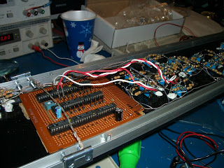
There are still many wires to run from here, but that was finished after this picture was taken. Now the front of the control panel needs to have the layout schematic placed on it. For this I used this vehicle pin striping which is cheap and very easy to work with.

And finally the finished product.

With the lights off.

Mostly red signals shown here with a few greens and yellows. All of these LEDs are the same bi-color device. The last step is to install the panel in the layout and wire all of the actual signal LEDs in parallel to the LEDs on this control panel. Once installed I will have pictures to show the final result.


