Showing posts with label bench. Show all posts

Sunday, June 12, 2011

Verifying LMR-200 Coax Cable Loss

For years I have used RG-58 cable for my antenna systems, it is inexpensive, easy to work with, and for short runs it works just fine. Last year I started heavily receiving NOAA weather APT imagery using the same RG-58 cable. During this time, pass after satellite pass I noticed my images were not as pristine as they should be. The cable length I was using was just over 100' in length and looking at the loss of my RG-58 it's no surprise that I had such poor images. As a test I replaced all of the cable with a used length on Andrew LMR-400 cable which resulted in an instant improvement.

Now this past week I finally mounted a wide-band scanner antenna on my home and needed a 60' run of cable to reach my RF bench in the basement. Instead of going to my typical spool of RG-58, I wanted something better. LMR-400 was my first choice but is significantly more expensive than my free RG-58. Because of this and the fact that a smaller diameter cable would be better hidden on the outside of the house I chose LMR-200. I purchased 60' of Times Microwave LMR-200 (arguably the best cable you can buy).


With an attenuation of 9.9dB @ 900Mhz, it was significantly better than RG-58. This cable combined with quality Amphenol SMA connectors I was curious to see if the cable would measure up to it's spec sheet. Times Microwave rates it's LMR-200 at 9.9dBm of attenuation at 900Mhz over 100'. At my 60 feet I should only be seeing 5.94dBm of loss which is what I am looking to verify.

The test setup:


An HP 8656B signal generator would be the test source while the spectrum analyzer in my HP 8922H would be used to verify the attenuation of the cable. As a baseline test, I connected a small 1' high quality 50 ohm SMA cable with Amphenol connectors in between the signal generator and spectrum analyzer. Using a -50dBm baseline, the measured signal through the cable was -50.52dBm at 100Mhz. At 900Mhz, it was -51.65dBm, a good start. Now to place the 60' of LMR-200 inline. Unfortunately I did not have a male N to female SMA adapter so I could not test the cable directly inline. To make the test work I placed a mini-circuits ZFSC-2-5-S splitter inline of the cable.


According the the mini-circuits datasheet, at 100Mhz this splitter has a loss on each output of 3.25dBm. At ~900Mhz it has a loss of 3.57dBm, both of which will be compensated for in the results. So testing the 60' of LMR-200 through the splitter at 900Mhz yielded -59.95dBm:


Taking that result and subtracting the loss of the mini-circuits splitter you end up with -56.38dBm, and the difference of that from the original baseline of -50.52dBm at 900Mhz is -5.86dBm of loss at 900Mhz, which is under the spec sheet of -5.94dBm by .08dBm, a very good result indeed. I love it when numbers work out. As a final test I ran a sweep test on the 60' cable using an HP 8754A Vector Network Analyzer. As expected, the loss from 10Mhz to 1300Mhz exactly matched the expected attenuation in the datasheet:


I will be running this cable to my antenna tomorrow. :)

Friday, September 17, 2010

My Electronics Bench and Test Equipment

I have been into the electronics field since I was about 11 years old. I reached that phase of my life where I began taking everything apart and wondering what all this 'stuff' inside these electronic devices was. It wasn't too long until I began understanding and learning while making my own analog and digital designs come to life. Eventually I reached a point where my current tools were just not allowing me to really debug and see what was going on inside the circuit I was designing. This is where I realized I needed better equipment than what I had.

Throughout this post I am going to talk about the equipment I own and what you should look for if just stating out in electronics. With all of the equipment available on the used market, anyone beginning in electronics that is taking it seriously should have the basics: A good multimeter, a soldering station, and a current limiting adjustable power supply. Without these three items frustration will only ensue.

We all start somewhere and my start was with a $9 RadioShack soldering iron and a couple dollars more analog multimeter. While the meter suited me fine for a very long time, the $9 fire hazard was the most frustrating piece. I remember at the time reading my Radio Electronics (later Electronics Now) magazine and looking in the back advertising sections at the nice Weller soldering stations and amazing test equipment that was being made by companies like HP and Tektronix. I had only wished that I could have even a 20Mhz oscilloscope but with my non-existing income as being in middle school allowed, I had to settle for some basic test equipment like the multimeter I had.

My break came in 7th grade when one day I happened to notice that my science teacher had an oscilloscope in the labs storage closet. I questioned my teacher about it only to learn that it didn't work and had been there a very long time. To my surprise my teacher said I could have it if I wanted it which I enthusiastically accepted. It was a very old Bell+Howell model, most likely a kit originally. It had only a couple Mhz bandwidth and upon opening it was full of tubes. The issue it had was there was no horizontal sync, only a single dot burning a mark into its crt upon power on. I immediately pulled all the tubes and went to a local tv shop which I had remembered still had an old tube tester in the back (this was like 1993, tubes were still very obsolete). I tested all of the tubes and found a few that were definitely bad and purchased replacements. Upon powering on with new tubes in place, I finally could see into the time-domain of the circuits I was building. The 555 timer oscillator circuit I could finally see the waveform being generated. From my 1Mhz crystal oscillator I could see a near perfect square wave with a 50% duty cycle. It was a very exciting time. This only fueled the fire for things to come.

I dealt with basic equipment all thorough college, but once I had a job and could finally afford good test equipment, I went at it full force. It is amazing to see how cheap test equipment has become, especially on the used market.

Here is the current test equipment that I own as this is my current bench as it exists today:


A nice big workspace is key, I personally like deep desks which allow me to place bigger items far away from me without taking up valuable local workspace. I built the bench shown above as I was not able to find any workspace that nicely fit my needs. They do exist, but can cost a considerable amount of money. I built my bench with a strong shelf to hold most of my test equipment right at eye level, it had to be considerably strong as some of the older test equipment can weigh 60 pounds or more each (HP / Agilent builds things very well ;) ). Also shown is an anti-static mat as it it important to not destroy your expensive components before you get to use them. Now to talk about the equipment itself:

Multimeter. The absolute most important piece of test equipment for anyone. In my opinion this is the first thing anyone interested in electronics needs to buy. I use Fluke multimeters as they are the best, hands-down. I have a Fluke 77 II shown here along with a Fluke 73 (not shown). Need to see exactly how much voltage that power supply is putting out? Need to see how much current this circuit is really drawing? Need to see how many ohms that resistor really is? A multimeter has the answers. A good multimeter will pay for itself the first time you don't blow up the circuit you are working on out. I also still have my original Micronta analog multimeter and use it every now and then. Analog multimeters have the benefit of being able to see slow voltage changes over time by watching the needle move. Hook one up to an 110V outlet in your home to see what I mean, it shows a slow voltage inconsistency that a digital meter cannot easily display.


Soldering Iron, a good one. This is the 2nd most important tool anyone interested in electronics needs. An adjustable temperature one is best, especially dealing with temperature sensitive smd components. You are able to turn the temp down when needed, but also have the ability to crank it up when soldering or desoldering components on huge ground planes. I like Weller, but there are many good brands out there. A digital display is nice for being able to see what the current temperature is set at. The Weller below also has an anti-static tip to make sure you don't destroy any devices from rogue static charges on the iron itself.

Oscilloscope, the standard piece of test equipment when you are serious in electronics. I have many of them. An analog scope with decent bandwidth is still an extremely important piece of test equipment as it allows you to look into the time domains of signals to see what is really going on. The Tektronix 2246 seen here is an awesome scope. This is the scope I go to most even with the several digital scopes I own. Analog scopes are simply better for viewing complex analog waveforms such as a video signal. Everyone needs at least one good analog oscilloscope. I have talked about the benefits and disadvantages of analog vs digital scopes in previous posts, but it will deserve much more discussion in it's own dedicated post. If you are looking for your first scope, go for a 40Mhz to 100Mhz analog model IMO. It will serve you well. Above the Tektronix in the pic is a Racal-Dana 1992 1.3Ghz frequency counter which I will discuss shortly.


Digital oscilloscopes are extremely awesome as well. The one shown on the bottom here is a HP 54503A digital oscilloscope. it is a 500Mhz 4-channel digitizing oscilloscope. This is the scope I go to most when dealing with high speed digital signals. The 500Mhz bandwidth allows me to see very high speed repetitive signals easily.


The scope below is one of my favorites, an HP 54112D. It is a digital scope similar to the 54503A above, but offers may comprehensive triggering options. It is often used for glitch detection, where you are looking for an anomaly in a signal. Because it has digital storage options, it is able to store any waveform once the specified trigger has been hit allowing me to see what happened. This was very useful during the design of my own custom ttl based cpu last year.

Make sure you do not skimp on the scope probes! A good set of probes can easily cost more that the scope itself when buying used. A quality passive probe from HP / Agilent or Tektronix that is matched to the scope it will be used on is a must, especially when dealing with high speed signals. Using a cheap generic probe will distort the signal being measured and not truly represent the signal you are viewing on it's display. A cheap probe can also actually inject noise into a circuit destroying the signal you are attempting to observe. Pay attention to the probe attenuation factor as well. A 10X (attenuated by ten times) probe is good for most cases, but be aware it will be difficult to look at signals under about 10 millivolts with one. Be sure to compensate any passive probe before use, otherwise your signals could appear distorted.


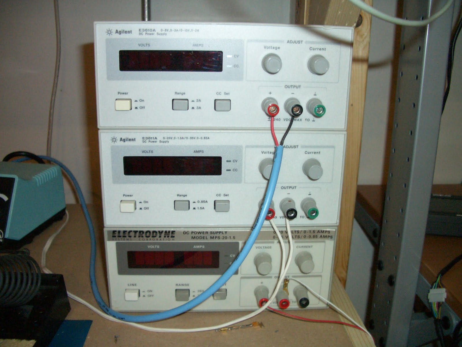
Power supplies. These are actually more important than a good oscilloscope for the beginner. An adjustable voltage, current limiting power supply will keep you from destroying your circuits in the event of a mistake. I have five of these and use them for everything. The ones below are all HP / Agilent models and are my favorite for the money. They are all adjustable voltage and current limiting which means you can prevent any load from drawing too much current. This is important because most power supplies can provide several if not many amps of current per given load. If you were to make a mistake in wiring your circuit and power it up with a non-current limiting power supply, you can plan to have that circuit go up in smoke. With supplies like the Agilent E3610 and E3611 shown below, you can set the current limit to N millamps / amps so that if there is a mistake it will protect your circuit from destroying itself.

I have seen some people modifying computer ATX PC power supplies for bench use and this is ultimately a horrible idea. Since they cannot current limit, using the 5V output on them could provide a huge surge current to your circuit before the power supplies protection circuit can go into effect , instantly blowing it up in your face. A current limiting supply will pay for itself the first time you make a mistake.


Logic analyzers are very important if you work with any type of digital logic. When I was designing my own CPU from scratch, this was an invaluable tool. Think of them as oscilloscopes, but differing in the fact that they can view many channels at once (think 16 to 128+ channels) and can only show states as defined per voltage thresholds for 0's and 1's over time. Basically if you need to watch many channels at once for lengths of time (a data or address bus), then to store the data... a logic analyzer is the answer. The HP 16500B shown below is my favorite with a color display and touch-screen control. It is a modular system allowing you to populate it with the boards you need. I picked mine up (I actually have three of them) from a local Dovebid auction fully populated. I had to get two of the three working, but now have a logic analyzer capable of up to 2Ghz resolution. I am only using one, keeping the others for spare parts. They are excellent tools for any digital design debugging and hardware hacking project.


PIC Programmers. PICs are my microcontroller of choice. I use Atmels and FPGAs as well, but PICs are my favorite. I use them in probably 75% of the projects I make. They are cheap, powerful, and with MPLab IDE free from Microchip along with their C compiler, I can have a working circuit in minutes. There are two programmers I use, The PicKit-2 and ICD-2. The PicKit-2 was my first programmer and still serves me well. It can program all devices with exception of PIC24, PIC32, and dsPICs. This is where the PicKit2 comes in, handling the more powerful smd PIC devices. Both have in-circuit programming capability which is nice as well. To program my microcontrollers, I have several computers at my bench. Today it is essential to have at least one for looking up component datasheets to programming your devices with your favorite IDE.

Breadboards, have had them forever and are so nice for prototyping. I use them all the time. I have many as often I have many projects going at once and don't want to scrap a circuit to start a new one. Be sure to have good wiring kits as well, nothing sucks more than not having the correct length wires to build a circuit.


Now it is time to talk RF. I love making RF filters and amplifiers and to test them you need good, stable RF generators. The two shown below combined cover all frequencies between 10Khz to 2.4Ghz. Each can be modulated with AM or FM carriers. The HP 8656B is a much newer unit with digital controls. It has option 001 (high stability timebase) which provides extremely accurate frequency generation. The model on top is an HP 8614A frequency generator which is older than I am. I picked this up on eBay for an amazing $20 and it works perfectly. It is an analog monster utilizing a klystron tube for RF generation.


A spectrum analyzer. This is the piece of test equipment I have wanted more than anything. Unlike an oscilloscope that lets you view into a signals time domain, a spectrum analyzer allows you to view a signals frequency domain. In the world of RF design, a spectrum analyzer shows you everything you want to know. The HP model 8922H below is actually a GSM / PCS cellular test set, but has option 006 which is a 10Mhz to 1Ghz spectrum analyzer.


Frequency counters are extremely useful for measuring frequencies in oscillators or any clock / RF source. The one shown below by Startek is a handheld model designed for sniffing out transmitters and other RF sources. It can also be used with a good probe to measure frequencies of any clock or RF source up to 2.4Ghz. Earlier above I showed my Racal-Dana bench top frequency counter which has a higher resolution then the Startek. I use both to measure RF frequencies in clock sources, RF sources, and to make sure any frequency is what it is supposed to be. You can use an oscilloscope (provided it's bandwidth is high enough) to measure frequency too, but frequency counters usually have much higher resolution.


Second bench, this bench is just spare space with a Tektronix TDS-420 digital oscilloscope and analog current limiting power supply. I use it for quick testing of devices when my main bench is full of clutter. Also seen is a small parts cabinet, and plenty of spools of chemicals, solder wick, and solder (use ROHS solder!, lead is not good. Yes, solder with lead does flow better but you will get used to the non-lead stuff).


More work space, of course completely cluttered, but more space is always needed. The dry erase board in background is always fun for drawing up new ideas.


This bench is where I work on enclosures and any type of metal or plastic work needed for a project. By far a drill press is the most used tool I own. The band saw and newly added milling machine help considerably when working with aluminum and plastic parts for enclosure panels.


The parts rack is the goto place for components. Keep everything you have organized so you spend less time looking for components and more time actually working on designing and assembling!


Wednesday, November 18, 2009

Moving day, projects on hold

The downturn in the economy has created some amazing deals in the housing market around me. Because of this I have purchased a new home and will be moving next week. This will of course put my projects on hold, I definitely have a lot of packing to do...

The really good news is that my new home has a huge basement which will allow me to have much more room for my current cluttered work area. :D


Monday, April 13, 2009

Remote GPS tracker + Accelerometer

This summer there are a few projects I have planned. One of the first is a model rocket tracking / data-logging system for some launches I am planning on performing this summer. I recently came across a good supplier of F and G series rocket engines for a very reasonable price. Some of these engines have as long as a 7.8 second burn making them very exciting to see take off.

The idea of this project is to be able to record all acceleration of the rocket throughout the the entire launch. The tracker will also have a GPS receiver that can log it's maximum altitude as well as track its decent to aid in finding it's landing location in the event of a launch where the rocket landing ends up not being visible. This GPS data will be transmitted through a long range Xbee tranceiver.

The basis of the performance data is an Analog Devices ADXL accelerometer. These accelerometers are very cheap and very accurate. They are available in different models with varying degrees of g resolution. The model I am using here is the ADXL330, a three axis +- 3g accelerometer.

The +-3g of resolution is fine for testing, for the actual rocket launch I will be using a +-18g accelerometer to capture launch and decent data.

The ADXL is a pretty small SMD device, so soldering was a little tricky:


The prototype I am making here is a testing base that will be used for debugging and developing the base station receiving software. I envision making a simple and cool app that will control and display all functions of the rocket from launch to landing. The design is based around a PIC18 series microcontroller. Initial performance testing and range testing will be performed by mounting this prototype to a remote controlled truck to gather data.


The tracker under development on my bench:


The finished prototype:

Please note that this device is much too big and heavy for use in a rocket. The final version will be made mostly of SMD devices on a PCB I design using Eagle. Lithium Polymer batteries will be used to save weight as well as using a smaller GPS receiver. I need to be able to save every gram of weight possible.


The device is currently working flawlessly as I have tossed the device around outside my home and been able to capture the data from it. Truck testing will occur this coming week or two, I will be able to display actual data at this time.

Sunday, April 5, 2009

Long Range XBee PRO

Digi recently released a new series of XBee wireless long range transmitters which I have been very excited to play with. The XBee-PRO 900 series has up to a 6 mile range using a high gain antenna! Some other features from the XBee site:
  • Fast 156 Kbps RF data rate
  • Point-to-multipoint networking ideal for low-latency applications
  • Support for large, dense networks
  • 128-bit AES encryption
Jim cam over this past weekend to help me perform some basic ranging tests with these modules to see what type of distance can be achieved in an urban area. The plan was to set up a base station and send messages out to a mobile XBee PRO as a repeater and see how far away we can get without dropping any packets.

The base station is simply an XBee PRO linked to my bench machine through it's serial port via a MAX232.


The mobile module is simply an XBee PRO with it's TX and RX lines wired together forming a basic echo repeater. Lithium polymer batteries are being used through a 3.3v regulator. This is simply in basic mode as well, no API mode.


Using Digis' useful X-CTU application for range testing, we were able to get some impressive results. We were not able to get anywhere near a 6 mile range, but with the fact that we were using only the on board whip antenna on these modules instead of a high gain antenna, it was expected. Our testing environment significantly limited the range as well because of the amount of concrete structures in the area. With all of this we were still able to reach a range of several thousand feet before packet loss. A standard XBee would never reach this range.


Range was very limited to line-of-sight. If there was a building in between the source XBee and repeater XBee, packet loss would occur in a very predictable manner. This was all happening from the source transmitter being on my bench inside my home, so there was already an initial structure blocking it's signal path.

Our next tests will occur in a more open area which will allow more line-of-sight testing. I am confident that we will reach several miles in this scenario and will report our findings.

Monday, November 17, 2008

New PIC Programmer

My new Microchip PIC programmer arrived today. I have been meaning to get a USB powered version for awhile now since my new bench machine only has two serial ports... causing the rs-232 real estate to be rather limited. (plus I can't use my ISA serial cards in machines now that the ISA bus is pretty much obsolete ). Instead of going the expensive option, I went the cheap Chinese option and ordered a PICkit2 compatible programmer off of eBay. It took about two weeks to arrive directly from Honk Kong, but it's here and it works.

Of course after opening the package I noticed that it was missing the ZIF sockets. :(


Looking back at the auction I see that this was stated in the description in a non-descriptive Chinese kind of way. Luckily the sockets are cheap and I ordered them from a reputable supplier today.

This will allow me to start using the surplus of samples I have been ordering for free and let me explore the PIC world a little more. I have been spending a lot of time in the AVR ATmega world for the past month or so (most ATmega's don't require a programmer) so it will be cool to compare and contrast the two micro families.

Sunday, October 12, 2008

Tektronix TDS-420 oscilloscope external video display

A nice feature of the Tektronix TDS series of digital storage oscilloscopes is their external video display capability. Most (if not all) Tektronix scopes in the TDS series have an external video output (including my TDS-420) for hooking up an external display.

The internal display is very nice:


Sometimes it would be nice to have a larger display at my bench level while working...

Unfortunately this external video output is in a 9-pin form, unlike the standard DB15-pin connector we are familiar with on our VGA monitors. Because Tektronix labeled the connector as 'VGA compatible', I assumed it held to the VGA standard, and would be compatible with most modern multisync monitors.


To hook up an external display to your TDS series oscilloscope, you must perform the following. Obtain a standard 15-pin VGA connector cable and remove one end, replacing it with a standard 9-pin connector (preferably a metal connector to help with shielding). Wire the new 9-pin connector to the VGA cable as listed here. The 15-pin connector is on the left with pin assignment to the 9 pin on the right:

VGA DB15-S Female DB9 Female
15-pin, 9-pin
1, 1 Red
2, 2 Green
3, 3 Blue
4, - Monitor ID bit 2
5, - N/C
6, 6 GND
7, 7 GND
8, 8 GND
9, - N/C
10, - GND
11, - Monitor ID bit 0
12, - Minitor ID bit 1
13, 4 Horizontal Sync
14, 5 Vertical Sync
15, - N/C

I tied pin 6 on my 15 pin connector to all three grounds (6,7,8) on the 9 pin connector. After assembly of the connector, I gave it a try with success!


One of my Samsung Syncmaster 151v lcds on my bench sync'd up perfectly along with several other lcd monitors I have around. With the output being 640x480 there is plenty of resolution on the display giving the external monitor a very nice picture.

Sunday, July 13, 2008

Plant watering system

For the past few years I have been growing various cayenne and habanero peppers in planters off of my condos balcony. The only issue with this besides lack of space has been watering. Previously I have been simply filling several large containers with water and carrying it out to the plants. This is fine in the beginning of the season, but by late July and August when the plants are large and consume much more water, this has been a chore. Multiple watering trips are necessary as well with watering them both in the morning and night. For a solution, I built a simple microcontroller based system that I could automatically water the plants on a set cycle. It also has a simple rain detector that preempts any further watering for a set amount of time after it has rained.


I designed the system around a Rabbit RCM3400 core 8-bit microcontroller. Realistically this microcontroller is rather overpowered for this system, ( a pic would have worked just fine) but I wanted to begin playing with the Rabbit's cooperative multitasking functionality... and I have a few of these micros laying around. There are a couple neat features of this micro as well such as the real-time clock and built in ADC's. For functionality, the rabbit drives a serial LCD for displaying current information on the system and has 5 microswitches along with a rain sensor for input. The system drives a latching relay which then turns on a 12v solenoid based electronic valve to start the water flow to the plants.

This is final stage of prototyping. It has been working fine for the past five days so I am beginning to build it into an enclosure this week.


The system has two adjustable parameters, frequency of the watering cycle and duration of the actual watering. The five microswitches will be placed under the lcd to allow the lcd to show the functionality of the buttons. I plan on adding a more robust menu setting that will allow control for multiple plants in the future. The left two adjust the watering frequency in hours, the next two can adjust the watering duration in seconds. For my small plants, 20 seconds or so of watering is enough to saturate the soil. The final button on the right is a forced watering function that allows me to provide a 15 second burst of water without resetting the current counters.

Once timing parameters are set, the micro begins counting down to the set watering time. The display shows how many minutes are remaining to the watering cycle. When the counter hits zero, one of the outputs fires for 250ms, enough to engage a latching relay which in turn opens the solenoid valve to start the water flow. Once the set watering duration is counted down to zero, the relay is fired for another 250ms to disengage it and cut power to the solenoid valve stopping the water flow. The process then starts over.

The rain detector is just two thin strips of aluminum foil spaced closely together on my balcony railing. When rain falls and closes the connection, a pin on the micro goes high letting it know rain is detected. The watering process is then put on hold for a set amount of time until watering begins again.


Now for a water source, I tapped into the cold water supply line underneath my sink. This is my only real option as I don't have any access to outside building watering on the top floor. The water is split with a tee fitting and ran to a solenoid valve. From here I ran a line out to my plants. Through a series of different tubing lengths and tees I was able to get an even watering distrubution among all three plants. The actual water is supplied to the plants through a polypropylene tube with a series of holes drilled through them.

The system works quite well.

Future upgrades will add control for multiple plants, and a better timing interface so I can set more precise watering cycles. If I want to go all out, I will enable the rabbit's ethernet interface to pull down real weather data automatically and have the micro set the watering cycles based on that day's conditions...

Tuesday, June 17, 2008

Homemade GPS Antenna

I needed a very small, lightweight passive GPS antenna for an ET-301 USGlobalSat GPS module, but didn't have anything to use on-hand. I started some research to make one but information on this topic is very limited... so I figured a good option would be to make my own. As far as passive antennas go, there doesn't look to be very much too them. I looked at lots of pictures of antennas online and reverse engineered them as best as I could. The result was an antenna made out of a thin piece of metal that is 24mm x24mm located 2mm over a 30mm x 30mm ground plane.

Now i'm not an RF engineer, and basic antenna math fails me on this antenna design (1/4 wavelength at a gps frequency on the L1 band of ~1.5Ghz would be 50mm) which is much larger than the antenna I designed mine after... but upon power up I had GPS lock.

So it works... which really shows how sensitive modern GPS receivers are. This is really amazing since this module is sitting inside, on my bench, located about 6 feet away from the nearest window... and I made the antenna by copying antenna designs I found online. The NMEA $GPGGA string shows that there are only 4 satellites in view (which is expected since I am indoors) so I am really looking forward to testing it outside.

At some point I hope to find a good resource for GPS antenna designs to really make a proper antenna the right way, but for now it works... and I am still impressed by the sensitivity of this receiver.

Tuesday, June 10, 2008

Cooperative multitasking

Sitting down this past weekend for a large amount of time to begin a new project (details will be provided in the next post)... I discovered an amazing feature with Rabbit Semiconductors microcontrollers. Cooperative multitasking. I have actually always known about the multitasking capability of these processors, but never actually used them in any real form.

Cooperative multitasking unlike preemptive multitasking has many benefits. For one, variables can be easily shared among different tasks. This simplifies the necessary code needed immensely as you don't need to take any necessary precautions while sharing variables in a typical interrupt driven preemptive environment. Cooperative multitasking also allows many tasks to be run at once (as they only appear to... time slices are actually given to each function running just like in any modern multitasking OS). The microcontrollers also take advantage of the natural delays that occur in most code execution to provide cpu cycles to other tasks.

Playing with this multitasking environment I was able to update information on an LCD via an array of switches in real-time, without taking any time away from any other running timers or processes. It essentially allows me to run several tasks at the same time while providing data input without the necessity of any type of interrupt. This is extremely powerful.

I have nearly finished the code for the current project tonight, I hope to have the project finished by the end of the week as an update to what this project is will be given upon completion.

Sunday, June 1, 2008

Clean Bench :)

There hasn't been an update for awhile, but I have some projects in the works. This weekend I finally had time to clean my bench so there will be some updates soon...