Wednesday, November 18, 2009

Moving day, projects on hold

The downturn in the economy has created some amazing deals in the housing market around me. Because of this I have purchased a new home and will be moving next week. This will of course put my projects on hold, I definitely have a lot of packing to do...

The really good news is that my new home has a huge basement which will allow me to have much more room for my current cluttered work area. :D


Thursday, October 22, 2009

Recovering a HP 16500B Logic Analysis System From a Failed Hard Drive to a CompactFlash Drive.

In a recent auction I purchased two HP16500B logic analysis systems and one HP16500A system for pretty much next to nothing which had me very excited. I have been looking to upgrade from my current 1630D logic analyzer to something a little more powerful. My 1630D has been excellent and has worked perfect for many tasks, but I have been finding that I have needed a more powerful analyzer with a lot more memory depth for some recent hardware hacking projects i have worked on. I have wanted to buy a 16500B system as their prices are reasonable, but the hard drives that they use have scared me. These hard drive based systems are ticking time bombs. Once it's disk fails the device is useless unless you have the original system boot disks for it and a working floppy drive.


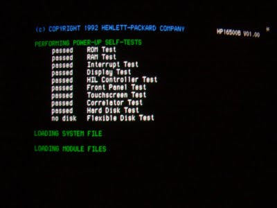
The price of these three systems I bought was next to nothing, and having local pickup as an option saved me a ton in shipping as these devices are by no means small or light. So even if they were all dead I wouldn't be that upset. Upon arrival home and powering them all up, one of the three worked. The 16500A has a power supply issue and will be looked at soon. I was really interested in the two 16500B systems which one worked perfectly while the other had the common 'HARD DISK FAILURE' error upon boot indicating a dead hard drive. Luckily both of these systems came with a full (unopened) floppy disk set of the system software which lets me boot the system with the failed drive from the floppy. While I was able to successfully boot the system, unfortunately many of the modules in it have been upgraded which my disk set didn't support leaving these feature modules useless.

These systems use a Quantum PI16A011 hard drive of 170MB capacity (at least both of mine did, later earlier or later models may have had different disks). Now while I probably had a box of these drives 10 years ago or so, I have since thrown them all away. I figured purchasing one would be easy but the only similar ones I found on eBay the sellers wanted a premium for them because they were 'vintage'. Whatever, I'm not paying you $40 for a 15 year old hard drive that will probably just fail again. Looking for a more permanent solution I decided to give a Compact Flash card a try in the device.

CF cards have the cool ability to mimic a hard drive in CHS mode ( cylinder / head / sector) . I have saved many failed firewalls and other embedded devices by replacing their failed hard drives with a CF card using a CF to IDE adapter card. You can find these adapter cards for around $5 to $10.

To get the data onto the new system I considered pulling the good drive out of the working 16500B and throwing it in a linux machine along with the CF card IDE adapter. I could then clone the disk using the 'dd' command to the CF card making an exact copy. Since I had already backed up all the data from the working 16500B to my network in fear the the working one would die, it was easier for me to just ftp this backup data over to the failed system.

Here is how I was able to recover my 16500B system with the failed drive by replacing it with a CompactFlash card:

1. I booted the good working system and configured the network interface for an IP on my network. This allowed me to ftp to the 16500B, logging in with the user 'control' and no password. I then copied over all files on the 16500B system via ftp get to my local computer. I now had a backup of all of the system software for safe keeping. (Note: If using an ftp application such as LeechFTP, or any other that allows threaded ftp functionality, make sure only one thread runs at a time. Trying to transfer more than one file at once will cause the 16500B to lock up) Note, Note! If you have a 16500B, back up it's software to your network! When that drive fails you will need this data to recover.

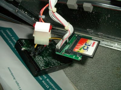
2. I purchased a CompactFlash to IDE adapter to use in the 16500B with the failed disk. I had to try several of them before I found one that worked with the 16500B. (Buy a quality one, not a cheap Chinese one. Make sure it also has a jumper for master/slave configuration and set it to Master).

3. Buy a CompactFlash card and place it in the adaptor. I used a 64MB card in my 16500B successfully. These cards follow the basic CHS (cylinder / head / sector ) format of older hard drives so it works fine. Avoid cards larger than 256MB as the 16500B may not recognize them ( I haven't tested, just my assumption. I do know for sure that my 64MB card works perfect).


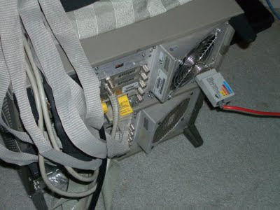
4. Place the adapter in the 16500B with the CF card installed. You will need to come up with your own mounting system to hold the new CF adapter in place where the hard drive was located. Connect the IDE cable and power connector to the adapter. Make sure it doesn't short out to the chassis ground.


5. Power on the 16500B and boot it via the system floppy disk. During boot, it will still report the 'HARD DRIVE FAIL' error message, this is normal.

6. In the 'system' menu, select 'hard disk' then select 'format' and press 'execute'. It will prompt you twice to confirm and format within a few seconds. If you have any errors here try a different CF card or adapter. Again, I had to try a few different ones to find one that worked.

7. Configure your 16500B's network adapter for a free ip on your network. Place an AUI media adapter on the 16500B and hook up to your network. It now should be pingable from another computer.


8. FTP to the 16500B's ip and login with user 'control', no password. You should login successfully. Now copy over all of the HP16550B's /system files from your backup to the 16500B with the CF card. If your CF adapter has an LED activity light, it will be blinking showing the data is indeed being copied. This may take up to 15 minutes to complete. If you only have the backup floppy disks, copy them to the CF card via the 16500Bs interface. I find it much faster to copy the floppies to a computer and ftp over all the data. The /system directory is the important one you will want to copy over.

9. Once all files are copied, remove the 16500B's floppy disk and power cycle. Upon boot, the hard disk should pass the self test and it should be immediately booting. Your 16500B is now ready for use!


Now CF cards do have a limited lifespan as well in regards to the amount of writes they can do, but since my 16500B just reads the card to boot, it should last a very long time. I'll still have to compare the CF card to the hard drive to see if there is any speed benefit in boot time to using the CF card. These are very powerful and excellent logic analyzers that are well worth converting to CF cards to increase their lifetime. Remember, if you have a working 16500B system, back up it's software before it's too late!


Thursday, October 1, 2009

CPU From Scratch

I haven't been posting too much lately, mostly because I have taken on a very ambitious project. I have decided to create an entire CPU from scratch using only TTL based logic. This project has been in the works for about two months now and I finally have something to show for it. Because this project is going to be more in-depth than most I have dedicated an entire wiki to it which can be located at bradthx.net.


As it stands now I have an 8-bit CPU that is able to load and store instructions into address and instruction registers from memory. This proves (along with a lot of additional debugging) that my design seems solid and I can begin designing my opcode and burning it to eproms. I will update this blog when I make major milestones, but all the technical data will be located at bradthx.net.


Sunday, September 20, 2009

Power Supply Reverse Engineering

I recently came across a crazy good deal on eBay, a Scientech SP1000 precision balance / scale. For $15 I couldn't refuse the purchase of a retail $2000 precision scale even though I knew the power supply was not included with the unit. I figured I could just reverse engineer the circuitry to create my own external power supply ( $100 retail value for the power supply from Scientech) to be able to use the scale, and after an hour on my bench my assumptions were correct.

I have wanted a simple scale for awhile now to measure the weight of rocket components to be better able to predict it's performance with my addition of GPS / accelerometer payloads. There are a ton of cheap scales on eBay (mostly from Chinese suppliers) but I knew I wanted something better and more precise than the average drug dealer who purchases these cheap items. After some research I discovered Scientech was one of the leaders in precision balances and began to search for them. I was very happy to find one for very cheap with the absense of a power supply. This is where my reverse engineering began. The scale had a 5-pin din connector for power. Knowing that this was not going to be completely simple, I tore the unit apart.

To reverse engineer it's power input, I first located it's ground pins. I did this by locating known ic's and metering their ground pins to a pin on the power connector. Also noticing large ground planes on the board helped as well. There ended up being two grounds pins on this board. Two pins down, three to go. Once the two ground pins were identified, I went for non-ground voltages. The first I discovered was a +5v line. I traced the pins back through taces from some known 7400 TTL logic ic's and was able to identify a +5v input. So one pin from the power supply provided +5v.


Moving forward I was lucky to find a label on the board indicating -12V. I followed this trace back to the power connector and identified one pin as being definitely -12V. Another pin from strictly an assumption would be +12V. I followed the traces from this last pin around and discovered they followed the -12V traces to a regulator, indicating that my assumption was probably correct. Time to power up.


After making all connections to my power supply, i powered up the +5V line first. Pressing the power button resulted in the display turning on with '-----'. A good start. I set my +12V and -12V supplies to current limit at .1A as to not burn it out if I was wrong, and slowly raised the voltage on each. Once about 10V on each was hit, the device came to life. I had a working scale with the exception of some errors on display. With some testing I discovered it was just pissed because the measuring tray did not have the full tray on it (applying a certain amount of weight). Placing an object, pliers in this case, on the scale are powering back up it turned on completely and successfully. I just now need to design a high quality linear supply for it for +5V, -12V and +12V voltages.

It's interesting to note that this small wire-wrap wire:


Weighs a whole .053 grams. :D (uncalibrated of course, so give or take +-.01 grams)

Saturday, August 8, 2009

One sweet ADC, National Semiconductor ADC08100

I spent this weekend playing with a few analog to digital convertors I have been meaning to try out, one of which is the National Semiconductor ADC08100. The ADC08100 is an 8 bit 100Msps ADC with very low power operation. To test it out I have it clocked from a PIC18F4520 running at 40Mhz and has the output being displayed on a pair of HP hexadecimal displays. Input is coming from a small Murata pot whose voltage can be adjusted over the set range of 0V to +3V.


I plan on using these ADCs for everything from video capture in basic machine vision systems to any type of ADC that needs high speed accurate conversion that can offload the ADC operation from the microcontroller itself.

Sunday, July 19, 2009

Texas Instruments TMP100 Temperature Sensor

When looking for cheap and accurate temperature sensors for the next up and coming near space balloon project, I came across this great little device from TI. The TMP100. Tonight I interfaced these little devices with a PIC18F4520 via I2C and everything is working perfectly.


Some basic info about this sensor:

Resolution: up to 12bit
Temperature range: -55 to +125 degrees Celsius

I plan on using two of these to monitor temperature, one for the inside electronics temperature and one for the outside environment temperature.


Thursday, July 2, 2009

TCM8230MD Camera Images Within Reach

Last night I was able issue a start command over I2c to the TCM8230MD camera module to have it start sending images. I'm now receiving valid YUV 422 data off of the 8 bit bus along with the necessary clock and sync pulses.


This camera is definitely not the easiest thing to work with. The datasheet is not as clear I would have liked and the timings necessary for the startup sequence took a little bit longer to figure out than I had expected.


The next step will be to be to send the camera a few more control codes to lower the frame rate and resolution to get the data rate to a more manageable level for the pic. I'm hoping to capture and display my first usable image over the weekend.